In my previous post, I talked about setting up the A4988 stepper motor driver’s current/voltage limit.
Today, I finally got the stepper motor moving!
There’s just one thing that’s bugging me: the motor is a little loud 😅
So in the video below, I attached a delrin disk to the stepper motor. FYI, this delrin disk will be used for so marker bands — tiny medical metal rings — to be sorted on.
Not sure if this video captures the audio well 🤔 But there’s some buzzing sounds and crunchy-like noises.
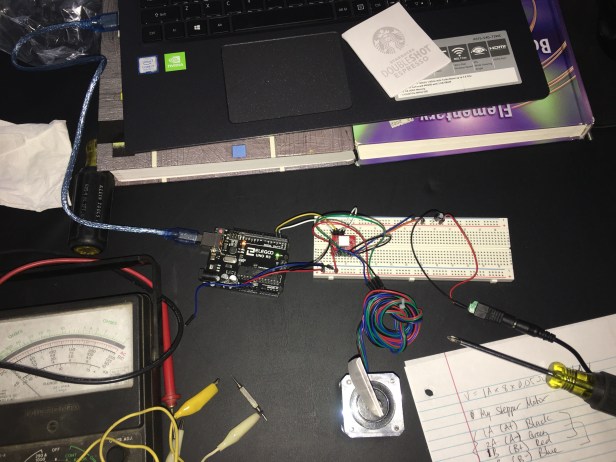
The Wiring
Ignore my messy table. But here’s the overall setup.
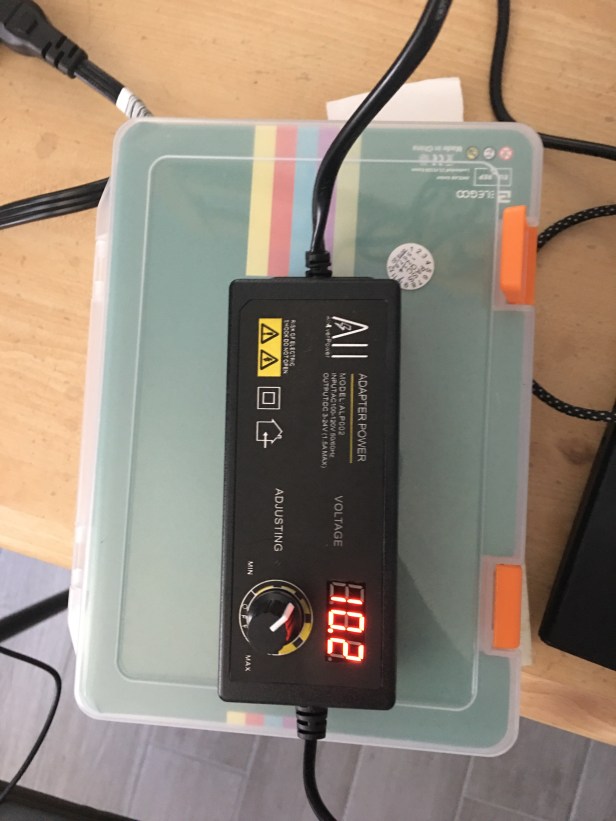
And below is a picture of the power supply I used. I have it set to ~10 V.
Maybe later on, I’ll use Fritzing or something to make a clean schematic. For my project, I’ll definitely use custom length wiring (instead of jumper wires) to make the electronics look prettier.
I learned something about my stepper motor!
I learned what this 1A, 1B, 2A, and 2B stuff is on a stepper motor!
This is stuff that has to do with the coils in a bipolar stepper motor. This guy does a fantastic job explaining what a bipolar stepper motor is (link).
There are 2 coils in my NEMA 17 Stepper Motor, and both coils have a positive and negative side. Therefore, 1A, 1B, 2A, and 2B are supposed to be paired up in a certain way in order to have the motor work correctly.
So for my stepper motor, it goes:
- Blue = 1B (B-)
- Red = 1A (B+)
- Green = 2A (A-)
- Black = 2B (A+)
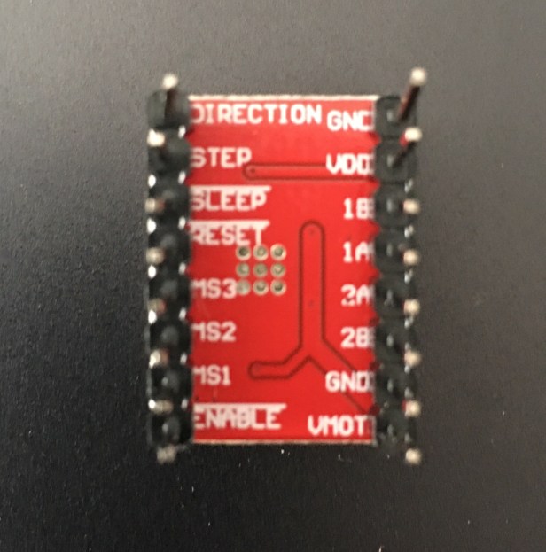
And the A4988 stepper motor driver board has convenient spots to hook up the corresponding coils (see image below)
The Code
The code I used to test my stepper motor is from DroneBot Workshop (link). Here it is below:
/*
   Stepper Motor Demonstration 4
   Stepper-Demo4.ino
   Demonstrates NEMA 17 Bipolar Stepper with A4988 Driver
 DroneBot Workshop 2018
   https://dronebotworkshop.com
 */
 // Define Constants
 // Connections to A4988
 const int dirPin = 2;  // Direction
 const int stepPin = 3; // Step
 // Motor steps per rotation
 const int STEPS_PER_REV = 200;
 void setup() {
 // Setup the pins as Outputs
   pinMode(stepPin,OUTPUT);
   pinMode(dirPin,OUTPUT);
 }
 void loop() {
 // Set motor direction clockwise
   digitalWrite(dirPin,HIGH);
 // Spin motor one rotation slowly
   for(int x = 0; x < STEPS_PER_REV; x++) {
     digitalWrite(stepPin,HIGH);
     delayMicroseconds(2000);
     digitalWrite(stepPin,LOW);
     delayMicroseconds(2000);
   }
 // Pause for one second
   delay(1000);
 // Set motor direction counterclockwise
   digitalWrite(dirPin,LOW);
 // Spin motor two rotations quickly
   for(int x = 0; x < (STEPS_PER_REV * 2); x++) {
     digitalWrite(stepPin,HIGH);
     delayMicroseconds(1000);
     digitalWrite(stepPin,LOW);
     delayMicroseconds(1000);
   }
 // Pause for one second
   delay(1000);
 }
Some things to note:
STEPS_PER_REV is the number of steps per revolution (in other words, increasing this number means more revolutions and vice versa).
Changing the number in delayMicroseconds will vary the speed of the steps (in other words, increasing the number will cause the speed to be slower).
Final Thoughts
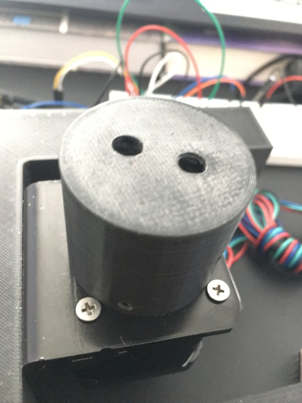
I think the loud noise might just be how the motor is. At first I thought it was due to our spindle (the black cylinder that is on the stepper motor shaft) rubbing against the screws on the stepper motor mount (see image below). But that wasn’t it.
One potential solution to reducing the loud noise is to try microstepping the motor. At the moment, my stepper motor is running on full step mode. Perhaps microstepping will refine the motor movement, and reduce the sound. My only concern is that it might increase power consumption and interfere with our camera (Pixy2 camera). But we shall see!
